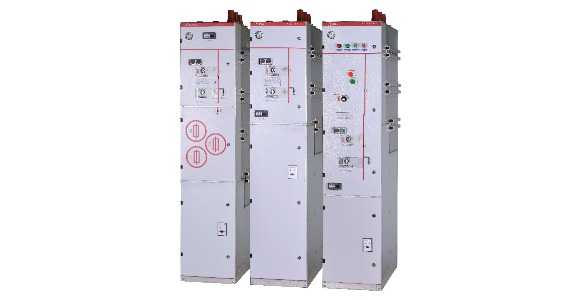
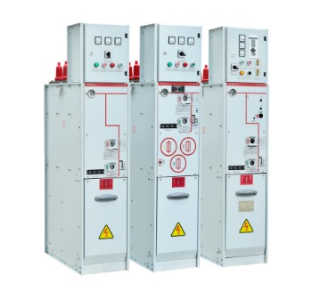
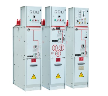
33Kv SF6 Electrical RMU
33KV sf6 electrical rmu (hereinafter referred to as ring main unit) is a 50Hz AC three-phase indoor high voltage power distribution equipment. The utility model is characterized in that the load switch, the grounding switch and the busbar of the circuit are sealed in the metal casing, and the spring operating mechanism is adopted, and the SF6 gas is used as a combination device of the arc extinguishing and the insulating medium.
33KV sf6 electrical rmu is applicable to the ring network power supply or double radiation power supply of the 33kV power supply line, which can change the original single radiation power supply mode. When the line fails, it can restore the transformer circuit feed in time, greatly improving the reliability and utilization of the power supply.
- Features
- Data Sheet
- Contact Us Now
Features of 33KV SF6 Electrical RMU
1. The 33Kv electrical RMU is composed of a switch room, a fuse room, an operating mechanism room and a cable room (chassis). 33KV sf6 electrical rmu is especially suitable for industrial commercial areas or rural towns and villages with large power supply load density and cable feeding network. At the same time, the ring main unit is safe to use, free from climate, easy to install, less maintenance and saves space. 33KV sf6 electrical rmu is suitable for installation in the prefabricated compact substation. The load switch or load switch-fuse combination device in the ring network cabinet can also be used in a separate cabinet.
2. The switch chamber is composed of various functional circuits (including grounding switches and load switches) sealed in the metal casing and bus bars between the circuits. The housing is welded from a 3mm cold rolled steel plate (or a non-embroidered steel plate). Each functional loop includes a load switch and a ground switch. The load switch is composed of a vertical moving contact system and a static contact at the lower end. When the switch is closed, the moving contact moves downward and the load switch is turned on. The grounding switch is composed of a movable contact knife and a static contact knife. During the movement of the spring, the grounding switch is quickly turned on. There are four rectangular assembly process holes in the upper part and the rear part of the switch room. The front side of the ring network cabinet is equipped with an observation window, and the “divide” and “close” positions of the grounding switch can be seen. An explosion-proof device is installed at the rear of the ring network cabinet.
3. The load switch adopts a compressed air blown structure, which has strong arc extinguishing ability and does not affect the phase and ground insulation. The moving and static contacts all have arc contacts, which greatly improves the number of breaking.
4. The fuse and the load switch chamber form a transformer protection circuit. The high-voltage current-limiting fuse is installed in the epoxy-insulated insulating case. After the fuse is blown, the striker is ejected and the load switch is opened.
5. The operating mechanism chamber is located on the front side of the ring network cabinet. In each functional circuit, the load switch is equipped with a manual (or electric) energy storage spring operating mechanism, and the grounding switch is provided with a human energy storage spring operating mechanism. They are used for the opening and closing operation holes of the load switch closing operation and the manual opening rotary knob and the grounding switch, the load switch minute and closing position indicator lights and the electric split and close button, and are provided with analog lines and switch states. The display card and the locked position, the operation of the load switch, and the grounding switch have interlocking devices to prevent misoperation.
| Ring6 33KV | C-module | F-module | v-module | ||||
| Switch disconnector | Earthing switch | Switch-fuse disconnector | Downstream earthing switch | Vacuum circuit-breaker | Earthing switch/ disconnector | ||
| Rated voltage | kV | 36/ 40,5 | 36/40,5 | 36/40,5 | 36/ 40,5 | 36/ 40,5 | 36/ 40,5 |
| Power frequency-withstand voltage | kV | 70/95 | 70/95 | 70/95 | 70/95 | 70/95 | 7D / 95 |
| -across disconnector | kV | 80/ 110 | 80/110 | 80/110 | |||
| Lightning inpulse withstand voltage | kV | 170/185 | 170/185 | 170/185 | 170 /185 | 170/185 | 170/185 |
| -across disconnector | kV | 195/215 | 195/215 | 195/215 | |||
| Rated normal current | A | 630/ 6301) | 200/ 2002) | 630/ 6301) | |||
| Breaking capacities | |||||||
| -active load | A | 630/ 630 | 200/ 200 | ||||
| -closed loop | A | 630/ 630 | 200/ 200 | ||||
| -off load cable charging | A | 20/ 21 | 20/21 | 50(Class Cl) | |||
| -earth fault | A | 60/63 | 60/63 | ||||
| -earth fault cable charging | A | 35/36 | 35/36 | ||||
| -transfer current | A | 840/750 | |||||
| -shart-circuit breaking current | kA | see3) | 20/20 | ||||
| Making capacity | kA | 50/50 | 50/50 | see3) | 2,5/ 2,5 | 50/50 | 50/50 |
| Class (Electrical endurance) | E3/ E2 | E2/E2 | -/- | E2/E2 | E1/ E1 | E2/E2 | |
| Short time current 1 sec.4) | kA | 16/16 | 16/16 | 1/1 | 16/16 | 16/16 | |
| Short time current 1 sec.5) | kA | 25/25 | 25/25 | 25/25 | 25/ 25 | ||
| Short time current 3 sec.5) | kA | 20/20 | 20/20 | 20/20 | 20/20 | ||
| Internal arc classitication IACAFL,1s | kA | 20/20 | 20/20 | 20/20 | |||
1) 400A for bushings Interface B (400 series plug-in) 2) Depending on the current rating of the fuse-link 3) Limited by high voltage fuse-links 4) Max. rating for bushings Interface B (400 series plug-in) 5) Valid for bushings Interface C


